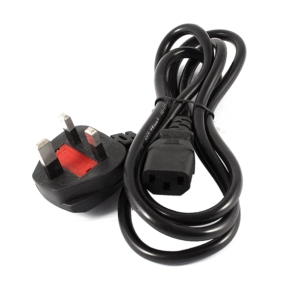
ARMORED SUBMERSIBLE Power CABLE

 In the example of FIG. 6, the cable 610 with the circular cross-sectional form has an area of unity and the cable 630 with the oblong cross-sectional form has area of about 0.82. As to perimeter, where the cable 610 has a perimeter of unity, the cable 630 has a perimeter of about 1.05. Thus, the cable 630 has a smaller quantity and a bigger floor area when compared to the cable 610. A smaller quantity can provide for a smaller mass and, for example, much less tensile stress on a cable that could be deployed a distance in a downhole surroundings (e.g., low voltage armored power cable attributable to mass of the cable itself). As proven in FIG. 6, the cable 610 features a circular cross-sectional form whereas the cable 630 contains an oblong cross-sectional form. In some embodiments, an insulation shield could also be strippable (e.g., to permit for termination and electrical testing of the cable). In the example of FIG. 10, the top assemblies form considerably "D" shapes (e.g., one being a backward "D") whereas the middle or intermediate meeting varieties a considerably elongated "0" shape.
 In FIG. 7, the instance cable seven hundred can embody EPDM insulation as the insulation 730, which can have a wall thickness of roughly 1.6 mm (e.g., roughly 0.065 inch), can embody a lead (Pb) shield as the metallic shield 750, which might have a wall thickness of approximately 0.6 mm (e.g., approximately 0.025 inch), can embrace crosslinked polyethylene as the cushion layer 760 and may embody metallic armor (e.g., galvanized) as the armor layer 780, which can have a wall thickness of approximately 0.4 mm (e.g., approximately 0.015 inch). As an example, in some flat power cable embodiments, two or more individual coated conductors might be arranged in a side-by-aspect configuration (e.g., consider configurations comparable to 2×1, 3×1, 4×1, and so forth.) and, for example, a number of armor layers may be utilized over a jacket. For instance, a barrier layer can be a layer exterior to a shield (e.g., an insulation shield layer) that may aim to offer extra safety from corrosive downhole gases and fluids. In the cable 630, the conductors 632 could also be about 7.35 mm (e.g., about 1 AWG) in diameter with insulation of about 2 mm thickness, metallic lead (Pb) of about 1 mm thickness (e.g., as a fuel barrier layer), a jacket layer (e.g., the layer 634) over the lead (Pb) of about 1 mm thickness at ends of the cable 630, optionally available armor of about 0.5 mm thickness and an elective polymeric layer of about 1 mm thickness (e.g., the layer 636 as an outer polymeric coat).
In such an example, the expansion may cause the cable 1000 to bulge such that the armor 1080 separates. In the example of FIG. 9, the edge 784 might be in direct contact with the cushion layers 760-1, 760-2 and 760-three where bending might happen of the armor 780 with drive in opposition to a number of of the layers 760-1, 760-2 and 760-3 the place the layers 760-1 and 760-3 may receive a greater quantity of the power than the layer 760-2. Thus, indentation danger may be higher for the layers 760-1 and 760-3, which could be thought of the outermost layers. In such an example, the polymeric layer 634 may encapsulate the three 1 gauge conductors and their respective layers the place, at ends, the polymeric layer 634 could also be about 1 mm thick. For example, as to the cable 630, consider three 1 gauge conductors (e.g., a diameter of about 7.35 mm) with varied layers. This was a sea cable that needed to withstand the pressures of the depth as well as assist its personal free weight throughout set up. Fatigue within the lead (Pb) barrier layer can be, a minimum of partially, resulting from cyclic stress and pressure as could also be caused by vibration of a cable throughout operation (e.g., consider fluid and/or motor induced vibrations).
As an example, a metallic shield layer may be applied over an insulation shield layer. According to an embodiment, one or more laptop-readable media could embrace computer-executable directions to instruct a computing system to output data for controlling a process. The SYNCURE™ system is a two-step, silane-grafted, moisture cross-linkable high density polyethylene system (XLPE). Therefore the excessive melting level of PP in comparison with that of XLPE contributes to improvement within the thermal stability and chemical compatibility of uncured XLPE. In some embodiments, a number of jacket layer compounds may be oil and/or water and/or brine and/or thermal and/or decompression resistant. PP has a better melting level than XLPE, which may provide thermal stability at a temperature above the melting level of XLPE (e.g., above approximately one hundred fifty levels C.) but decrease than the melting level of PP. As an example, armor can embody a strap thickness, which may be singly or multiply utilized (e.g., double, triple, etc.). In FIG. 7, the cushion layer 760 is exterior to the metallic shield 750 such that it will probably mechanically cushion the metallic shield 750. For example, the cushion layer 760 can mechanically cushion the metallic shield 750 from pressure that may be utilized by and/or carried out by the armor of the armor layer 780, which may be, for instance, a galvanized metallic armor.
Designed by sketchbooks.co.kr / sketchbook5 board skin
Sketchbook5, 스케치북5
Sketchbook5, 스케치북5
Sketchbook5, 스케치북5
Sketchbook5, 스케치북5